5 V DC Power Supply on a Custom PCB
Designed in EAGLE, etched, soldered — and then fault-found three times before it held 5 V
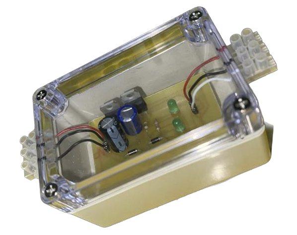
What
A mains-fed DC power supply built from scratch on a board we designed, etched and soldered ourselves. The brief was to take an AC source down to a fixed 5 V output using a full-wave rectifier with a centre-tap transformer — four stages in series: transformer, rectifier, filter, regulator.
It was the first project where the thing on the bench had to match the thing on paper, and the first time I designed a board rather than a circuit.
How
The supply steps 240 V down to a 12 V secondary through a centre-tapped transformer. Two 1N4004 diodes rectify both halves of the cycle, 470 µF capacitors smooth the result, and a 7805 IC holds the output fixed while the input line or the load moves. Two LEDs on the output make a failed regulator visible at a glance rather than at the multimeter.
Two schematics were drawn. The first put the regulator IC in a position that would have needed its own external supply, so it was discarded and redrawn — the second became the board. From there: breadboard first (it worked on the first try), then the EAGLE board layout, then the etched PCB.
Soldering is where the project actually happened. Three faults surfaced in testing, each found by working backwards from the symptom:
- The PCB ground was not carried across the whole board — solved by shorting the isolated section to a connected one.
- One of the two voltage regulators took its input but produced nothing at the output. Desoldered and replaced.
- An LED lit late, or not at all. The joint, not the part — reinforcing the solder fixed it.
Outcome
A working supply, verified stage by stage on the oscilloscope: sinusoid in, rectified ripple after the diodes, a flat line after the regulator. The measured output was 5.18 V rather than 5 V, which we attributed to instrument and human error and recorded as it was — an error margin we judged acceptable rather than one to round away.
The habit that stuck was the debugging order: prove the stage before you blame the stage after it.
Gallery
Click any image to enlarge